Concepts and terminology
Before starting to use Plant Modeller, make sure you are familiar with the following concepts and terminology.
Applications
Plant Modeller is a software package that contains the following executable programs.
-
Plant Modeller – The interactive main module that provides most of the needed functionality.
-
Component Modeller – For creating geometric instructions for COS objects.
-
Support Designer – For creating secondary and primary supports for piping.
-
Collision Detector – For detecting collisions between two sets of model objects.
-
Piping Isometrics & Spools – For managing isometric groups for piping.
-
Functional Model Template – For reusing structural units.
Project
Plant Modeller is operated in the context of a Project. The data describing a project is stored into two CADMATIC Object Storage (COS) databases: Project Database and Library Database. The first one contains data specific to an individual project, and the second contains data that different projects can share.

In the picture above, the Library Database is replicated from the Project (A) server to all the replica servers. Project (A) Database is replicated to two of the replicas, but not to the leftmost replica which is a Project (B) server and only includes the Project B Database. Root Server manages the common configuration for all COS servers in the network.
Project site
The actual design work takes place at a project site. Typically, there is a number of computers connected by a Local Area Network (LAN). COS Server hosts the project and library databases, and there is a shared directory that is accessible to all computers which participate in the design work at this project site.
When project administrator creates a new project, this action creates the main project site—the site that has the master database for this project. The library database can be master or a replica of the company library database.
If needed, there can also be satellite project sites that participate in the design work of a project.
Workspace
A workspace is a per-user directory that provides storage space for directories needed to run the CADMATIC applications in the context of a given project.
Before you can participate in the design work of a project, you need to have a workspace in the shared directory of one (and only one) of the project sites. This workspace is named using your login account name. Physically, this workspace can be located either in the hard drive on your local workstation (recommended) or on a file server. In the first case, IT administrator must be aware of needing to make backups from local workstations.
Design area
Design area provides the necessary per-user, per project site infrastructure that Plant Modeller requires to be able to run. Design area stores work copies of project data.
Physically, a design area is a directory in your workspace, and you can have several design areas in your workspace. Design area defines the limits of designer's rights to modify objects. Project space covers all areas (all model objects) in a project. View limits can be set smaller than the design area limits.

When you create new objects such as pumps and pipes, or modify existing objects, then these changes are first visible only to you in the design area in which you are currently working. Only after you save and explicitly request Plant Modeller to update the project database do these new and modified objects appear in the project database and become visible to other users.
Plant Modeller periodically checks for updates in the project database and updates the data in the design area accordingly.
Concurrent design is implemented so that to be able to modify an object you must check out the object to your design area. New objects that you have created are automatically editable (checked out to you) until you check in the objects. New objects that others have created are not available for editing until they check them in and you check them out. This guarantees that only one designer at a time can modify certain data.
Design tasks
Plant Modeller provides native support for the following design tasks:
-
Component modeling (pumps, valves, and so on)
-
3D plant design
-
placing of equipment, structural components, and beams
-
pipe routing, placing of valves and flange sets
-
placement of ducting components
-
set operations
-
3D viewing operations
-
attribute management
-
group management
-
-
Document production: drawings (elevations, sections, isometric and perspective views)
-
views generated from the computer model
-
annotation and dimensioning to show data extracted from the computer model
-
parametric 2D-symbols
-
automatic Bill of Material generation
-
-
Material lists and summaries
-
Collision detection
-
Isometric piping drawings
-
Interfaces to other CAD systems
-
Interfaces to maintenance systems
Core functionality is accessible from a script language. This enables third parties to write additional script applets for some special tasks that Plant Modeller does not provide by default. Also optional products built on top of this scripting interface are available from CADMATIC.
Piping terminology
Pipe geometry
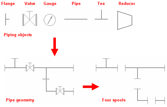
The geometrical model of a pipe consists of a set of piping objects that can be, for example, straight pipes, elbows, flanges, and valves that are joined together. The geometry can include all the components of the whole pipeline, or the pipeline can be divided into several separate geometries. Each geometry represents one isometric drawing.
A piping object represents its real-world counterpart with the following attributes:
-
Symbol (defined in the Piping Isometrics & Spools symbol map)
-
Geometry type, which defines the points to which other objects can be connected
-
Geometric location
-
Orientation
-
Other parameters defined in Dimension Tables
The pipe geometry can be divided into spools. A spool is a group of connected objects that are prefabricated as a unit and installed as one piece. If the pipe geometry takes too much space in isometric drawings, the geometry can be divided into smaller pieces for visual purposes (= splitting).
The picture below illustrates how piping components can appear in drawings.
Pipeline
A pipeline is a system of pipes, fittings, valves, and specialty components designed to transport fluids or gases from one piece of equipment to another.
A pipeline consists of one or more pipe runs.
A pipe run consists of one or more piping parts.
In the picture below, there are three pipelines: COLD_WATER, HOT_WATER, and GREY_WATER.
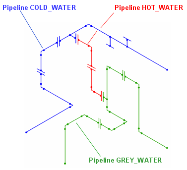
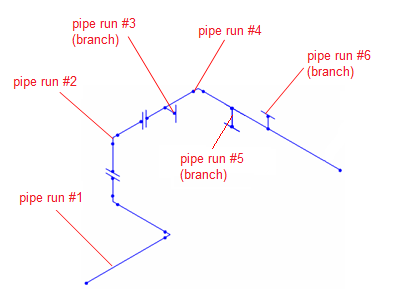
The pipeline COLD_WATER consists of six pipe runs: its main pipe consists of three pipe runs, and one of those pipe runs has three branches.
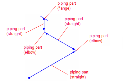
The first pipe run in COLD_WATER consists of six piping parts: three straight pipes, two elbows, and one flange.
Pipe run
A pipe run is a continuous set of piping parts that starts and ends with either a flange or a weld.
A pipe run can be (a part of) a main pipe or a branch pipe.
A straight pipe run is routed as a single pipe segment. Pipe runs that change their direction are routed as several pipe segments.
Piping part
Piping part is the smallest identifiable element of a pipeline. It can be a straight piece of pipe, an elbow, or a flange, for example.
Main pipe
A pipeline always has a main pipe. In addition, a pipeline can have branch pipes that are of equal size or smaller than the main pipe.
Branch pipe
A pipe that connects to the main pipe is a branch pipe.
Pipe segment
A pipe segment is the set of parts that a piping designer inserts between two consecutive routing points.
Pipe routing point
A routing point is a point where the pipe run starts, changes its direction, or ends.
Pipe spool
A pipe spool is a set of connected piping parts that are prefabricated, transported, and installed as a single piece of piping.
Pipe spool candidate
A pipe spool candidate is a prospective pipe spool that the program has formed based on predefined spool break rules, but which the user has not yet assigned to a pipe spool document.